


In part one, I discussed removing the pulley from the motor shaft, opening the case, removing the bearings, and selecting new bearings for the restoration. In part two, I will discuss the disassembly, wiring, and cleanup tasks. In an upcoming post, I’ll finish up with the rewiring and restoration of the motor.
For reference:


Craftsman 115.6962 1/2-HP Capacitor Start Electric Motor – Diagram. Source: VintageMachinery.org
Continuing from part one, I had loosened the end frames and pulled the rotor assembly out through the right side / fan side of the stator. This left the right side frame completely disconnected, but before I could remove the left side / terminal side end frame, I had to get in there and disconnect the machine screws holding the overload protection assembly/thermostat, centrifugal switch, and terminal block from the end frame.
Oh, did I mention that a family of dirt daubers had set up shop inside the motor at some point in the last 65 years? Dirt daubers, if you’re not familiar with them, are more-or-less non-stinging solitary wasps that build mud tubes that harden into incubation chambers for their larvae. They’re pretty cool, but not when they are nesting in your motor.

View through stator of left end frame with centrifugal switch in center. Terminal block is peeking out on the right side. Dirt dauber nest to left, covering the thermostat.
The wiring exiting the stator was extra crispy after 65 years, so it was important that I be very gentle with it, and avoid moving it more than necessary. A broken wire in the windings would essentially be impossible for me to replace or repair, so the motor would be junked if that happened.
So, I carefully chipped away at the dauber nest, and unscrewed everything I could get at, eventually removing the left end frame.

The dirt daubers left an unholy mess.
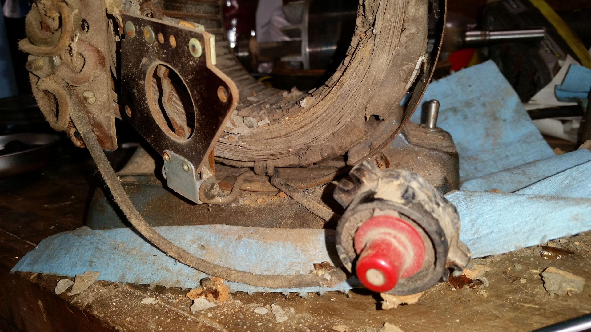
So what you’re looking at above is the terminal block on the left. That’s a little brown board with two terminal posts that are used to join wires that control the direction of rotation. In the center, you see the centrifugal switch, which opens and shuts based on motor speed, including or removing the start capacitor in the motor circuit. Then on the left, the red button is the overload protector assembly, that resets the motor if it overheats. You can see that the daubers left an awful mess.
Ugh.
I gave it a preliminary cleaning with a toothbrush. You really can’t be too gentle with these old motors.

The wiring, as I mentioned, was crispy and in pretty rough shape. I had to salvage the ends coming out of the riveted windings, since I couldn’t get in there to remove the end of the wire.
Let’s start with my wiring diagram. I’m not an electrician, but I think this gets the points across.
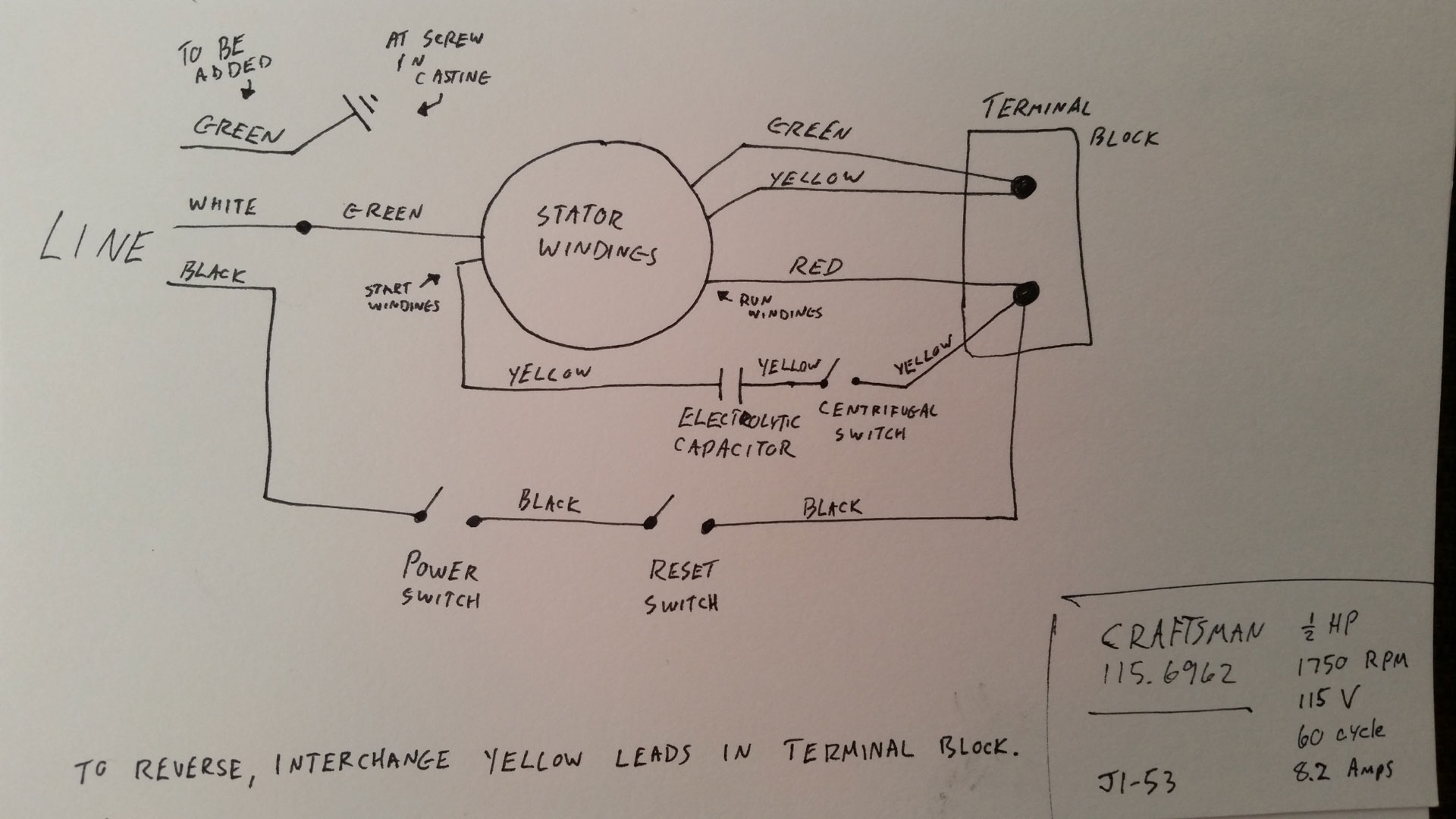
Wiring diagram Craftsman 115.6962
So we have a two-wire power cord coming in the back of the bottom frame to the underside of the motor (passing through a grommet and with a metal cord retainer). The original cord was in rough shape. It also lacked a ground, because grounds were for cowards in 1953, apparently.

Power cord was cracking and didn’t have a ground.

The power cord hot wire (black) goes to the power switch, and the neutral (white) goes into the wire nut and feeds into the windings via a green wire. No ground was originally provided.
I had removed a flat electrolytic capacitor that was mounted under a plate beneath the motor in order to access this lower bay. The capacitor was still kind of working, but I planned to replace it due to its age. It’s not currently shown, but it had two yellow wires going to the capacitor: one from the windings, and one from the centrifugal switch. The rusty bolt head is one of two 3/8″-16 x 5/8″ hex bolts that attach the stator assembly to the lower frame.
I may as well talk here about replacing the start capacitor. The start capacitor goes into circuit during the first few seconds of motor operation, bringing it up to speed. Then, at about 80% speed, the centrifugal switch opens and the capacitor is removed from the circuit. When the motor is switched off and slows down, you hear a clatter from inside the motor, which is the centrifugal switch closing again (it’s normal). The old style capacitors were flat, about 3 in. by 5 in. by bout 0.5 in. thick (book-shaped) and they are no longer manufactured in that form factor. I am replacing mine with a 130 – 156 MFD x 110 / 125 VAC start capacitor # 092A130B125AC1A (made in the USA by BMI) that I sourced from Amazon. It’s a cylindrical-style capacitor that is 1-7/16 in. diameter and about 3 in. tall. The original capacitor was a 124-155 MFD x 125 VAC x 60 cycle start capacitor, so the new capacitor closely matches those specs. You don’t want to go outside the MFD rating by more than 10%, but you can go from, say, a 125 VAC model to a 250 VAC capacitor.

Capacitor bay, capacitor removed. Both those wires should say ‘to cap’ – I labeled them wrong. On the right is the power switch. The striped metal band is part of the center band. The wires pass under the band.
So, back to the end frame wiring. There is a black wire from the power switch to the overload protector assembly, and a yellow wire from the capacitor to the centrifugal switch. Both pass through the gap between the motor interior and the lower frame.

Yellow wire from capacitor to centrifugal switch. Black wire from power switch to overload protector assembly thermostat.
A green wire and a yellow wire exit the windings and go to the terminal post marked ‘2’. A red wire goes from the windings to terminal post ‘4’, a yellow wire connects the centrifugal switch to post ‘4’, and a black wire connects the thermostat reset switch to post ‘4’. Swapping the two yellow wires between terminal posts 2 and 4 will reverse the direction of the motor.

Terminal block (foreground) and centrifugal switch (background).
Hopefully, the pictures and the wiring diagram make the wiring arrangement clear.
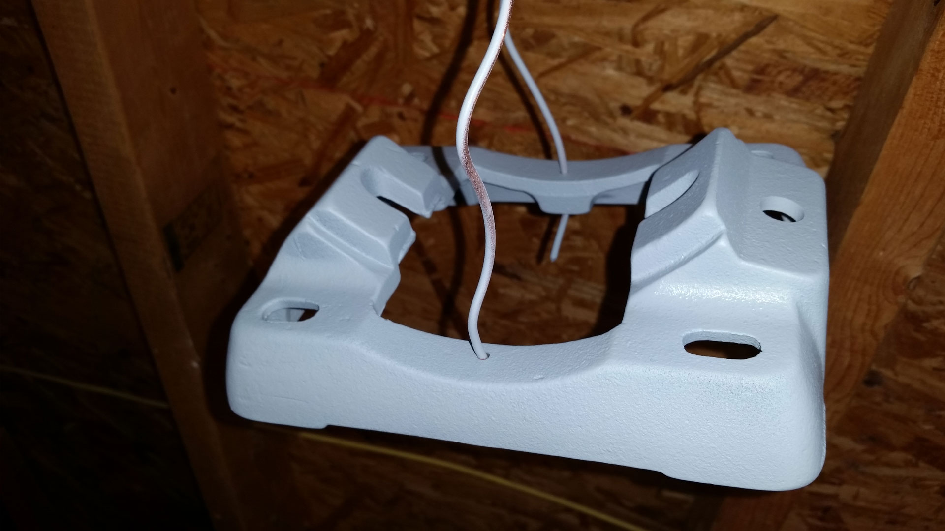
I proceeded to remove the stator assembly from the lower frame, and took the center band off. I had to cut the power cord, which I’d be replacing anyway.
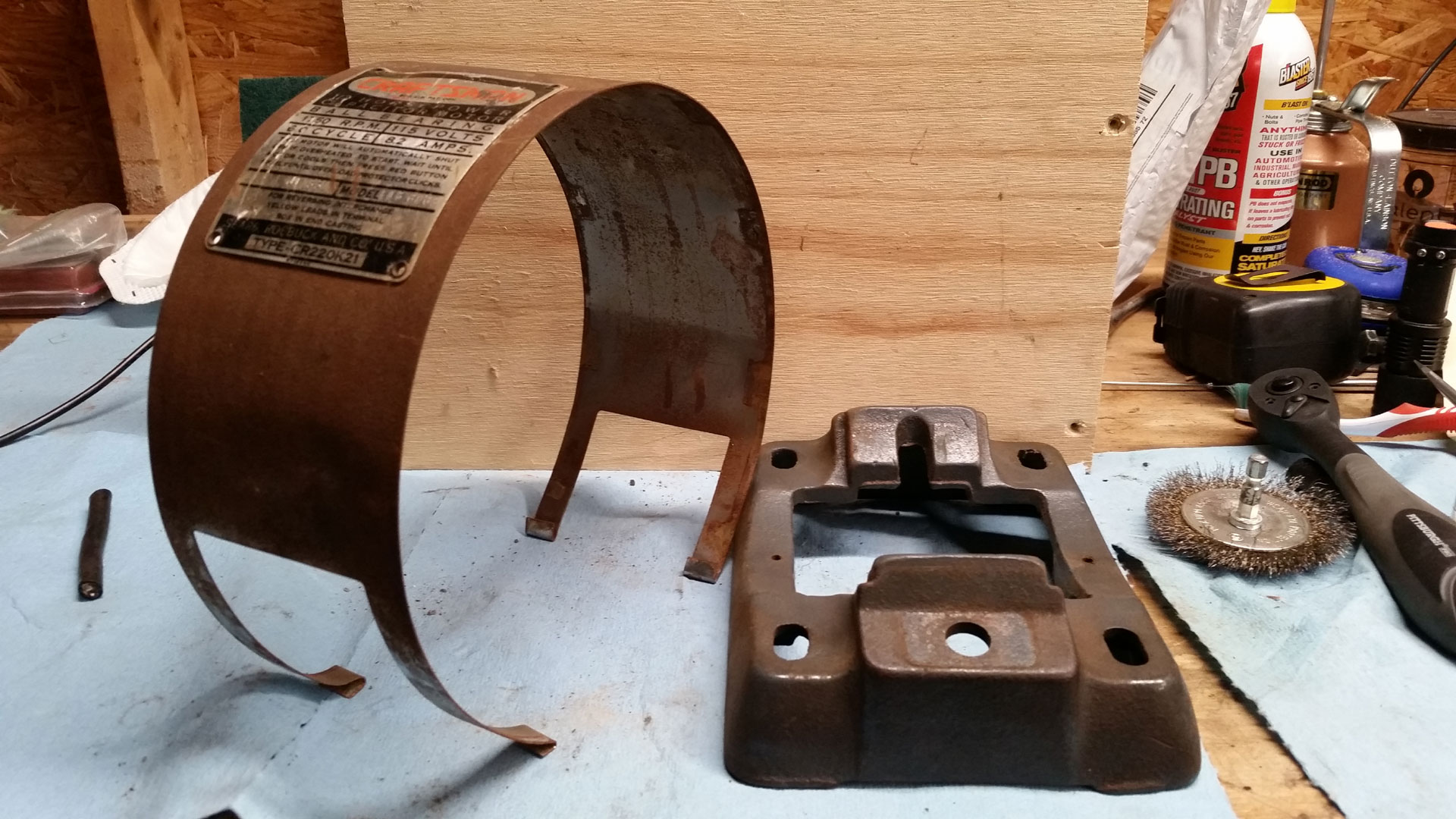
Lower frame and center band removed from stator assembly.
I stuck a couple of Q-tip sticks into the threaded holes in the lower frame and proceeded to media blast it. Then I cleaned it, hung it up, primed, and painted the lower frame.

Q-tip sticks are useful for plugging small threaded holes.
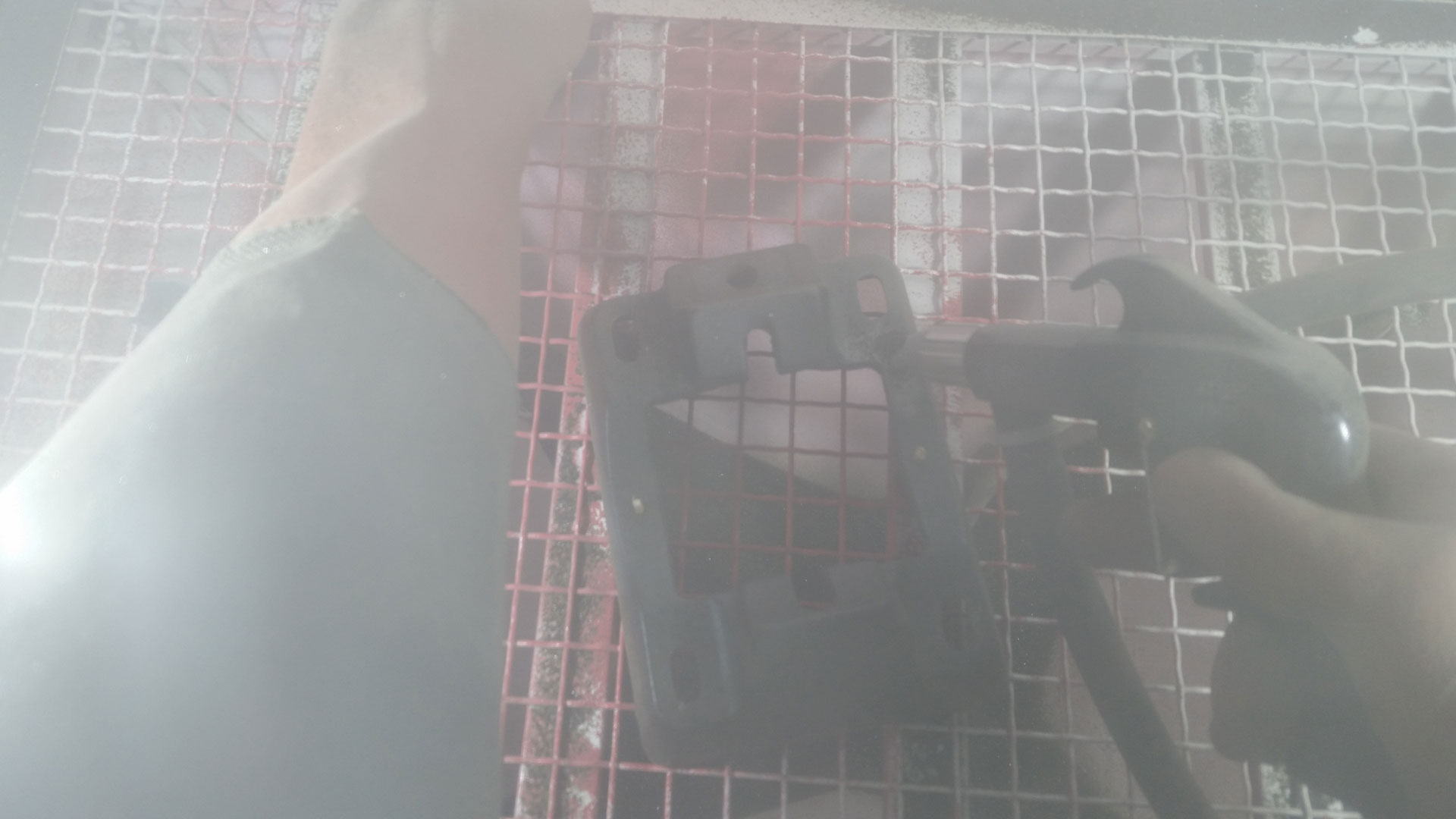
Media blasting the lower frame.

Blasted clean and ready for priming.
Primed.
I repeated these steps with the end frames, the terminal box cover, and the centrifugal switch shield. I’ll hold off on showing the final paint job until later.

Terminal box cover and switch shield during painting. And my messy garage.
Next, I cleaned up the fasteners. Mostly, that involved wire wheeling on one of my Craftsman block grinders.

The acorn nuts for the through bolt were #10-24 threaded, so I mounted them on a piece of threaded rod to hold them while wheeling.

Wire wheeling the acorn nuts for the through bolt.

I used another coupler nut with a small section of threaded rod glued in with locktite to make a holder that I could chuck in my drill. By mounting the drill in my vise, I could clean up the through bolts.

One polished up through bolt and the associated acorn nuts. The nuts were stainless steel, I think. They weren’t magnetic.

Most of the other fasteners were #8-32 machine screws. I used a Bernard parallel pliers to hold them while I wire wheeled the threads.

I used a #8-32 coupler nut and some threaded rod to make a holder for the machine screws in order to wire wheel their heads.

Before (top) and after (bottom) cleaning up the machine screws.
Well, I originally intended to finish up this post series in two parts, but this post is getting so long, I think I’ll save the electrical rewiring and reassembly for a third post.


Russ Boehm
A member of the OWWM.org site sent me a copy of the manual you posted but unfortunately it doesn’t show the wiring. I can’t seem to find anyone who understands how this capacitor should be wired into the circuit. As noted, the motor had been running for years (my dad gave me the saw in 1965!) but recently I noticed I was getting a mils shock when I touched another grounded machine in the shoop. I thought the replacement of the capacitor would be a simple swap but a year later I still had not gotten it done. I did not make a copy of the wiring and thus my problem.
If you can offer some suggestions, I would appreciate it.
Thanks for your post. By the way, this motor is pristine in comparison with what you had to deal with.
Russ in Colorado
Craftsman 1/2 HP Motor Wiring Problem
Postby rwboehm » Sun Apr 15, 2018 5:51 pm
I know you guys have never done this but I pulled the old capacitor on my Sears ½ HP Capacitor Motor, Type CR220K9, Model 1156963 when it shorted out. Thinking it would be a simple replacement, I didn’t bother to sketch the wiring out. Well, they don’t make the old style flat capacitor, 124-150 MFD, that fits inside the base of the motor and now, over a year later, I finally bought a can type capacitor, 124-149 MFD, and I’m trying to rewire the motor.
My success has been limited. I did get the motor to run but it blew out the capacitor. The motor continued running and could be stopped and restarted without a problem but I’m guessing that since both windings were apparently engaged constantly, it would either be inefficient or it might burn out the motor.
I chucked the output shaft in my drill press to test the centrifugal switch and here are the resistance readings I got across the various wires terminating in the base of the motor. The wiring from the motor consists of:
• Wire #1 = 16g black disappears into the motor
• Wire #2 = 16g white disappears into the motor
• Wire #3 = 12g brown wire disappears into the motor
Based on resistance, someone told me this is probably the Run winding
• Wire #4 = 12g brown wire that splits into two and disappears into the motor
Based on resistance, someone told me this is probably the Start winding
In the photos you will see the new three wire power chord I plan to use, the old chord was a two wire. As you would guess:
• Black – goes to the toggle switch
• White – remains to be seen
• Green – grounds out on the motor case
Note:
No capacitor in the circuit for these readings.
The old capacitor has two contact points that appear to be sized for a small wire gauge.
Craftsman Motor Ohm Meter Readings.jpg
Ohm Meter Readings
Photo #1 – Motor case opened to show the existing wires that terminate in the case. The orange wire is the new power chord noted above with black going to the motor’s toggle switch.
IMG_6212.JPG
Photo #2 Old Flat Capacitor – notice the wire connection size
IMG_6204.JPG
It’s hard to see if the ohm meter chart is posting well. I’ll try it and if not, I’ll find a different way to do it. Thanks in advance for any help you can offer.
Russ in Colorado
MP
Hi Russ,
Sorry I’m just now replying – I get an ungodly amount of spam on these comments, and your message got lost in it all. I’d suggest checking your centrifugal switch – maybe it wasn’t disconnecting the capacitor once it was up to speed? There’s a good book called Electric Motor Repair by Robert Rosenberg that you might find interesting. There are a number of editions going back (I think) to the 1950s or 60s, which is actually pretty useful, because that is the same era these motors were made in. I got a copy through my library.
I don’t see any of the photos you’re referencing, unfortunately. A short-circuited capacitor can damage the motor, so go ahead and get a proper replacement. I’m a little confused that it will still spin up with a blown start capacitor, because I would think that would interrupt the circuit to the start windings. If it can be manually spun up and then will run, then the problem would seem to be in the start circuit, which includes the capacitor, centrifugal switch, start windings, etc. I’d first try a new capacitor, make sure it wasn’t just a bad replacement. Double check all the connections, perhaps take a look at how my motor was wired on the blog. And definitely check out the Rosenberg book, because it’s great. Good luck!
Nathan Callon
I’m replacing the capacitor on the same model motor. The motor ran fine before I removed the capacitor, but now only hums and doesn’t spin with the new capacitor. I haven’t soldered the new capacitor on, because I wanted to make sure it worked. Shouldn’t the motor spin with both yellow wires making good contact with the capacitor?
MP
Hi Nathan,
Hm…I guess the first step is to recheck all your connections. Unplug it and make sure it’s turning smoothly by hand (could be locked up at the bearings if it’s been apart).
Make sure you replaced the start capacitor with another start capacitor (not a run capacitor) with the correct MFD rating. If you purchased the correct part, you could potentially have gotten a bad capacitor (it’s been known to happen), so maybe try swapping back in the old capacitor (if it worked) and see if it runs. If you can test the new capacitor with a multimeter, do so.
Since it’s humming, sounds like power is getting from the wall through the power switch, reset switch, through the centrifugal switch, through the capacitor, and into the windings. Don’t just let it sit there humming, or it will overheat the windings.